![]()
|
|
||||||||||||||||||||||||||||||||
|
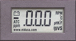
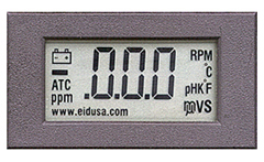
EID's Instrument Digital Snap-in 3.5 digits panel voltmeter:
Features: 3
1/2 digit, 9.5 mm character height display
200mV
full-scale input sensitivity (0-2000mV option) 10
pA input current typical Automatic
polarity Easy
panel mounting 14
analytical icons on display Easy
to use decimal point and icons 9V
or 5V operation Reflective mode
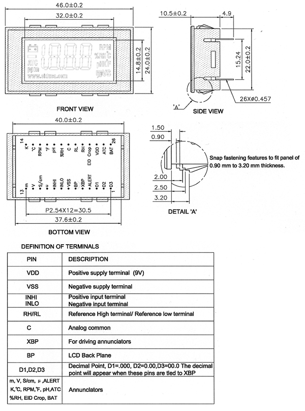
Specifications, Electrical Characteristics - Ta=+25°C
Drawings
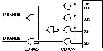
Applications notes: Over & Under range Signal
The
additional IC's which are required to generate the over range
and under range signal.
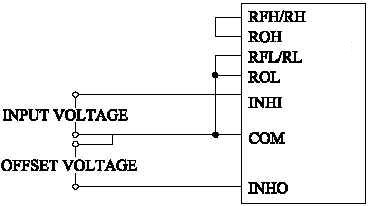
Zero Display for Non-Zero Input Voltage
If a zero display is required when the input voltage level is not zero, the offset voltage should be connected between INLO and COM, while the input voltage is connected between COM and INHI.
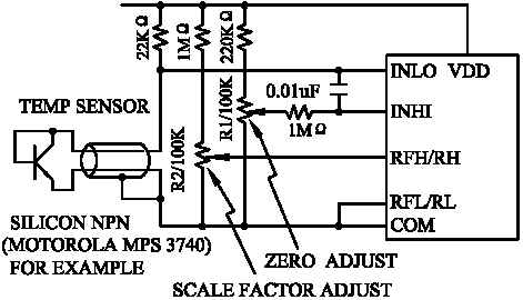
Over range & Under range Signal
A simple temperature sensor is an ordinary silicon diode or the base emitter of a silicon transistor. The forward voltage of a typical silicon PN junction change is -2.1mV/°C. Since the sign of the voltage change is negative, the diode voltage is applied to INLO to give correct polarity. R1 offsets the forward voltage drop of about 550mV causing the display to read 0.00 at 0°C. R2 adjusts the reference to match the slope of the diode voltage versus temperature. Ideally the sensor diode should be driven by a current source. Substituting a high value resistor will only add approximately 0.75°C of non-linearity. The resistor also slightly compensates for the reference temperature drift and decreasing battery voltage. To calibrate the circle, the diode sensor must first be immersed in a stirred ice water bath (0°C) and adjust R1 to 0.00 reading. Then immerse the diode in boiling water and adjust R2 to 100.0 reading.
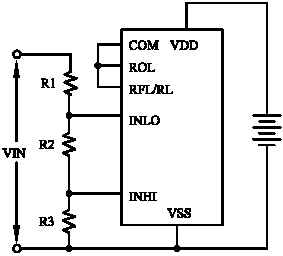
Non-Floating Supply
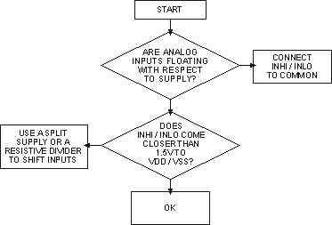
Figure (c)
A 9V battery is recommended for 9V operation. It is intended that the analog inputs (INHI / INLO) float with respect to the 9V supply. Please note, if a non-floating supply is required, some care must be taken. (Refer to the data sheet "200mV digital voltmeter" circuit). In general, if the analog inputs do not float with respect to the supply, the analog input must be no closer than 1.5V from either supply voltage (VDD / VSS). This can be done by using a (a) split. The flow chart in figure (c) will help to guide you to the proper solution.
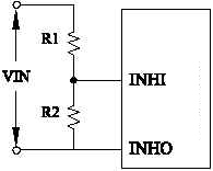
Input Attenuators
To
measure voltage greater than 200mV, an input attenuator is
needed
R1
+ R2 should be accurate and stable. Good metal film resistor
meet these requirements. The input attenuator reduces the input
resistance of the circuit from >10 ohms to R1+R2. A practical
upper limit is 9M
In multi-range applications it is necessary to also witch the decimal point. This can easily be accomplished by connecting the appropriate D1 to D3 terminal with a rotary switch to XBP pin ( D1=.000, D2=0.00, D3=00.0
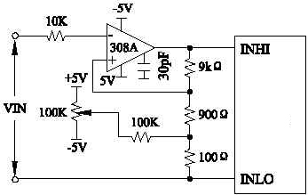
20mV Full Scale
An operational amplifier is used to measure full scale voltages less than 199.9mV. Note that the auto zero circuitry within the module cannot compensate for the op-amp offset or voltage drift.
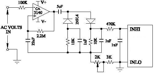
AC Voltage Measurements
The
module can only measure DC
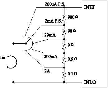
Current Measurements
The use of a shunt resistor converts the current to a voltage. The following formula can be used to calculate the shunt resistor.
A multi-range current meter circuit is shown. Note that although the input current passes through the selector switch, the voltage drop across the switch does not contribute to the measured voltage.
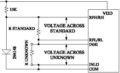
Resistance Measurements
The radiometric technique is used for resistance measurements. The unknown resistance is placed in series with a known resistor and current is passed through the pair. The voltage developed across the unknown resistor applied to the input (INHI, INLO). The voltage across the known resistor applied to reference inputs REH and REI. If the unknown equals the standard, the display will read 1000.
Due
to the radiometric technique, no accurately defined reference
voltage is required. The module will over-range for R unknown
Pricing
* Prices and product/sensor/cable colors are subject to change without notice. Additional 10% discount with student ID, USA only. |
||||||||||||||||||||||||||||||||
|
Description and SKU# |
Price 1-10 |
10-100 |
100-1K |
Picture |
||||||||||||||||||||||||||||
|
DVM 3.5 digits panel voltmeter 9V EID-D-LCD-35-200-9V (Old P#) new P# EID-DSP-LCD35-A001-9V |
19.75 |
14.95 |
9.95 |
|
||||||||||||||||||||||||||||
|
|
||||||||||||||||||||||||||||||||