![]()
|
|
||
|
MEET SEQUENCER, The fun and easy sequence LED kit, that shifts LED light from LED to LED!
Our SEQUENCER - S4 has many applications; simply power the board and light 4 LEDs start to "move," left to right again and again in sequence! This automatic sequence of blinking lights (LED) can be controlled directly from a front mounted multi-turns trimmer (pot.) and will draw attention and fun! The unique small design will allow you to mount it almost anywhere. Operate it with 6V, 9V battery, 12V car battery, four 1.5V batteries, or via one of our battery simulator kits. The alternative uses are endless. It’s designed for the beginner as well as the expert. Please drop us a line at sales@eidusa.com and let us know how you and your kids use your SEQUENCERS!
The SEQUENCER - S4 heart is the PIC micro-processor Integrated Circuit (IC) PIC12F675 (4MHZ version) by Microchip, Corp.
This kit is an educational electronics kit that allows one to customize the LED sequence rotation speed and more by changing the Analog to Digital Converter (ADC) via the voltage divider between VCC and ground in our case through multi-turns trimmer. YES .ASM and .HEX are AS-IS and provided for FREE!
One can program the PIC using PIC-KIT2 by Microchip Corporation directly from personal computer (PC) via Universal Serial Port (USB).
Note: The PIC 12F675 IC is 8 pin DIP, 14bit type Micro-processor with 4 Analog to Digital port and 6 I/O. Click here to download the the PIC 12F675 chip data-sheet.
Do It Yourself (DIY) Software driven micro-processor base kit, and have a blast!
|
||
|
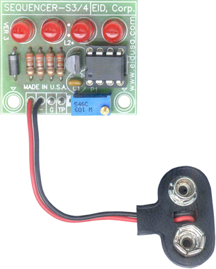
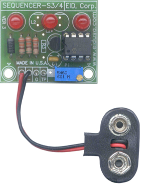
Shown above in a 4 LED Configuration Shown above in a 3 LED Configuration
|
||
|
Kit Includes:
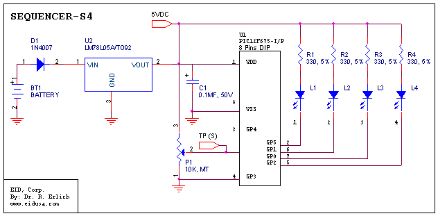
Schematic:
|
||
|
MEET SEQUENCER – Our alternating sequence blinking LEDs electronics kit. The kit is based on “PIC micro-processor PIC12F675. Using software code to control (turn ‘on’ and ‘off’) the corresponding LED. This basic kit can work with many conventional color LEDs; Green, Yellow or Red etc.
The 330 Ohms resistor determines the LED's brightness and limits the current flow to about 10mA when running with 9V battery. Standard LED will operate on 10-20mA and the voltage developed on the LED is about 1.6VDC, therefore:
R_Led
= (V_Bat – V_CE – V_LED) / 20mA =
The SEQUENCER flash rate is determined by P1 (10K multi-trimmer potentiometer) see schematics above. Changing P1 which used as a voltage divider will change the voltage on Test Point (TP) Signal (S) voltage 0-5V. This voltage then reads back to the micro-processor ADC and the software converts this value and changes the cycle time of the blinking LEDs.
|
||
|
Description and SKU# |
Price |
Picture |
|
SEQUENCER Kit EID-K-SEQ-UENCER-S3-ASM (Fully assembled) |
27.33 |
|
|
SEQUENCER Kit EID-K-SEQ-UENCER-S4-ASM (Fully assembled) |
29.07 |
|
|
SEQUENCER Kit EID-K-SEQ-UENCER-S3-KIT Kit Only |
24.93 |
|
|
SEQUENCER Kit EID-K-SEQ-UENCER-S4-KIT Kit Only |
25.92 |
|
|
EID-K-SEQ-UENCER-SX-PCB PCB Only |
12.87 |
|
|
|
||