![]()
|
|
||
|
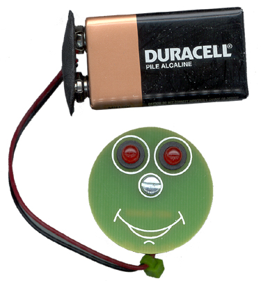
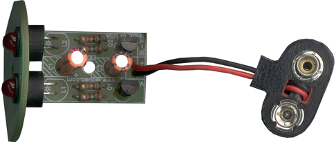
MEET BLINKER, the fun and easy blinking kit. Our BLINKER has many applications; fill your party with blinking BLINKERS. Mount the BLINKER on your bicycle so you'll be more visible and have a safer ride. Mount it on the car dashboard as an alarm flashing light imitator. Or mount it on your room door (i.e. please do not disturb). Place BLINKER anywhere you’d like to draw attention and a smile. The unique small design will allow you to mount it almost anywhere. Operate it with 9V battery 12V car battery, via two 1.5V batteries, or via one of our battery simulator kits. The alternative uses are endless. It’s designed for the beginner as well as the expert. Please drop us a line at sales@eidusa.com and let us know how you use your BLINKERS! |
||
|
(Both, smiley face and 9Vbattery are options)
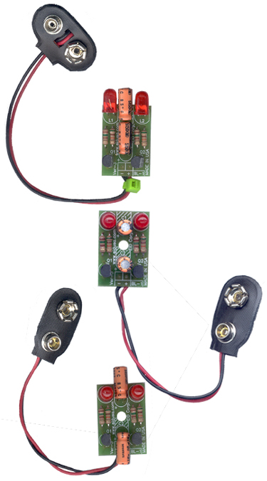
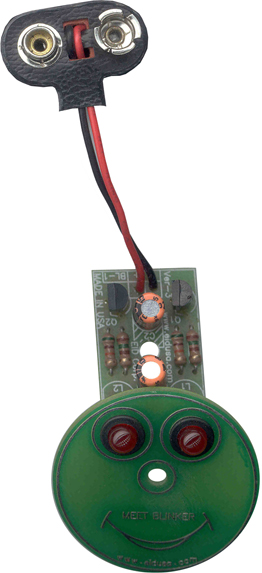
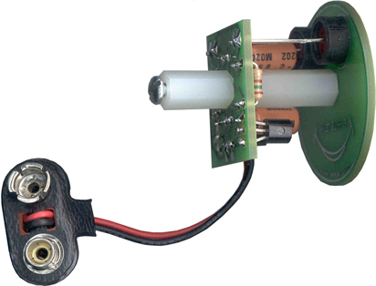
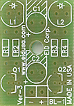
So many ways to configuration and mount the components, see above pictures. Mount your BLINKER almost anywhere.
|
||
|
Kit Includes:
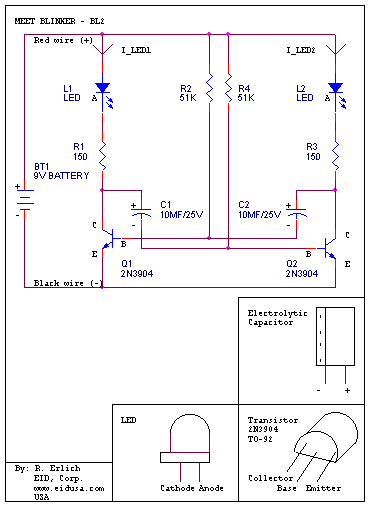
Schematic:
|
||
|
MEET BLINKER – Our alternating dual blinking LEDs kit is based on “a-stable-multi-vibrator.” Using 2 transistors as a power switch to control (turn ‘on’ and ‘off’) the corresponding LED. This basic kit can work with many conventional NPN transistors i.e. 2N3904, 2N4401, 2N2222, etc.
The 150 Ohms resistor determines the LED's brightness and limits the current flow to about 15mA when running with 9V battery. Standard LED will operate on 10-20mA and the voltage developed on the LED is about 1.6VDC, therefore:
R_Led
= (V_Bat – V_CE – V_LED) / 20mA =
The duty cycle (time on divided by the full cycle) of each transistor is less then 30%. Therefore, 0.3 * R_LED = 108 Ohms. Since the BLINKER is designed to be powered from 3VDC and up to 18VDC, we chose 150 Ohms resistors to limit the current through the LED’s for a larger range of operation. To get more lumination (light) from the LEDs, use smaller resistors. Please be advised you should never exceed the LED maximum current limitations. Doing so will result in burning the LED.
The BLINKER flash rate is determined by the 51K resistors, and the 10µF capacitors combination determines the ‘on’ time of each alternate transistor. Using matching components R1 = R4 and C1 = C2 will result in matching duty-cycles of the transistor, therefore the LED light time. The BLINKER flash rate is about 1 cycle per second. Additionally the 51K resistors are used to limit the current flow to the transistor base. Remember, the Ohm’s law... the larger the resistor, the smaller the current.
V = I * R
Finally, decreasing the blinking rate can be done easily by increasing capacitors size i.e. C1 = C2 = 22uF. Or on the contrary, using smaller capacitors value i.e. 4.7uF to increase the rate. Please be advised any capacitor use with this kit should carry 25V rating and above. Any modification you do at your on own risk.
Note: The 9V battery is for demonstration only and is not included in this kit.
|
||
|
Description and SKU# |
Price |
Picture |
|
BLINKER Kit EID-K-BLI-NKER-ASM Fully assembled EID-K-BLI-NKER-PCB Kit |
15.33 12.93 |
|
| EID-K-BLI-NKER-M1-PCB PCB Only | 8.88 |
|
| EID-K-BLI-NKER-F1-PCB Optional face PCB | 7.92 |
|
|
|
||