|
Industrial and Commercial OEM Power Multi Channel Solid State Relay, Triac and Bidirectional-Thyristor Dimming Module. The board control main supply input of 110/115/120/220/240 VAC, 50Hz, 60Hz & 400Hz, high current via opto-isolated, filtered multi-channel Triac dimming circuit. The module also includes built-in Zero-Crossing (ZC) detection signal generating circuit, Low Pass Filters (LPS), Resistor-Capacitor (RC) Snubber Circuit (SBC) for inductive load switching, and Voltage Transient Spikes Suppress (VTSS) circuit and more. Each power bank group units (Group of 4 Channels) and/or each channel separately fused externally via “off-the-shelf” Circuit Breaker (CB).
The Power channels Solid State Relay (PSSR) modules boards are used for fast switching VAC applications. Ideal for switching mains circuits, on/off dimming lights, appliances and small and large loads. Each circuit is isolated with opto-isolators circuit on each channel for both, CMOS or TTL inputs signals. The board trigger input 0 to 12VDC modulated signal that synchronized with the board zero crossing signal.
High Power Screw Terminal (PST) for Load connections (high voltage high current). Dedicated DB9 or RJ45 type connector for each 4 (quad) channels for easy, yet inexpensive remote connection of control signals (up to 15VDC).
The channels solid state relay (SSR) board also contains indication LED for Power On (PWR ON) visually indication of channel power on level.
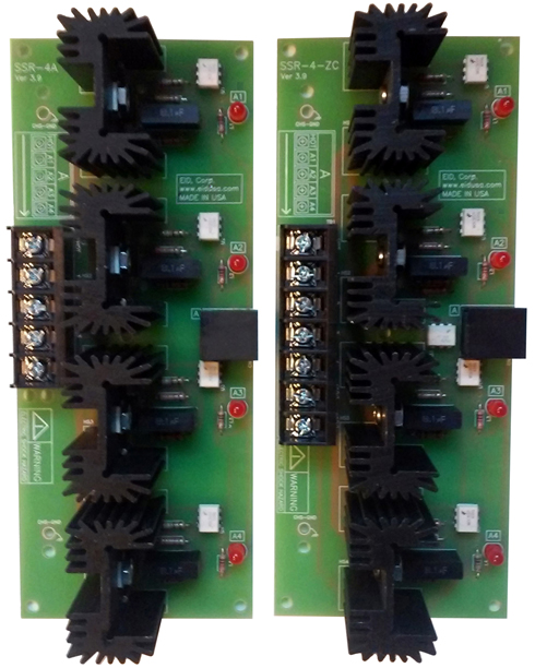
Shown above left, 4 channels solid-state relay modules boards with high current high Voltage configuration and on the right high current high voltage 4 channels channels solid state relay (SSR) with an additional Zero Crossing function configuration
The Multi channels industrial power solid state relay boards can be configured as lighting control modules. Each channel provides constant power dimming ability via zero-cross filtering to reduce lamp flickering.
Basic configuration channels solid state relay (SSR) boards are 4, 8, 12 & 24 channels designed for universal light dimming and home automation dimmers for incandescent bulb, LED , magnetic low voltage, electronic low voltage. Easy termination using high current, high voltage, high Power Screw Terminal (PST) conveniently mounted on the board.
Each GROUP is composed of four individual CHANNELS Triac type dimmers. Where; each channel is rated for 600 Watts (5 Amps), with a total group rating of 2400 Watts (20 Amps) when fed from separate 20 Amp 120VAC 50Hz or 60Hz feed via standard 15A, 16A or 20A circuit breaker that automatically protects the group from over-current, over voltage and shorts.
Mounting is easy via four 0.156" mounting holes supporting heavy-duty 3-32 type mounting screws. and wire (optional) via convenient conventional industrial standards locking connectors.
SSR-4A & 4ZC
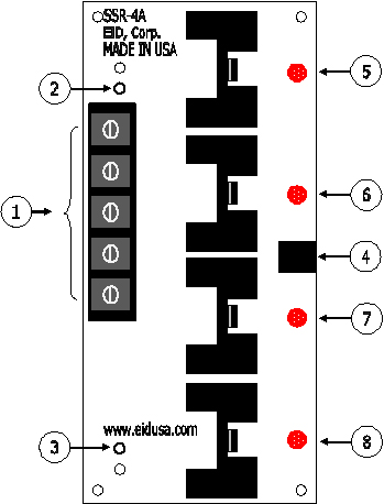
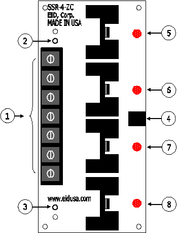
Shown above left, 4 channels channels solid state relay (SSR) with High current, high Voltage configuration and on the right high current, high voltage 4 channels channels solid state relay (SSR) with an additional Zero Crossing (ZC) function configuration Interface Board Module basic connections illustration
1. POWER High Power Screw Terminal Group A model SSR4A (front view top to bottom) VAC-HOT, OUT-A1, OUT-A2, OUT-A3, OUT-A4. Model SSR4-ZC (front view top to bottom) VAC-HOT, OUT-A1, OUT-A2, OUT-A3, OUT-A4,VAC-(N), VAC-(N).
2. Chassis Earth Ground (CHS-GND) place for soldered wire optional.
3. Chassis Earth Ground (CHS-GND) place for soldered wire optional.
4. RJ45 Signal Input Group A: 1-VCC, 2-CH-A3, 3-CH-A2, 4-CH-A4, 5-CH-A1 and ZC signal output. 6-ZC-GND, 7-ZC-GND & 8-ZC-OUT
5. Group A, Channel A1 LED indication
6. Group A, Channel A2 LED indication
7. Group A, Channel A3 LED indication
8. Group A, Channel A4 LED indication
WARNING ELECTRIC SHOCK HAZARD!
Please be advised, that all of our Solid State Relay (SSR) board should be served and install & connected, only by license trained engineer!
SSR-8AB:
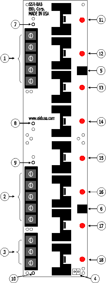
Shown above left, 8 channels solid-state relay (SSR) modules boards with high current, high voltage configuration and on the right high current configuration Interface board module basic connections illustration. On the right the 8 channels channels solid state relay (SSR) board picture.
1. POWER High Power Screw Terminal Group A (front view top to bottom) VAC-HOT, OUT-A1, OUT-A2, OUT-A3, OUT-A4.
2. POWER High Power Screw Terminal Group B (front view top to bottom) VAC-HOT, OUT-B1, OUT-B2, OUT-B3, OUT-B4.
3. POWER High Power Screw Terminal (front view top to bottom) VAC-(HOT), VAC-(NTL), GND.
4. POWER High Power Terminal Block output for low voltage transformer to dirive computer (CPU) board (front view left to right) VAC-(HOT), VAC-(NTL).
5. RJ45 Signal Input Group A: 1-VCC, 2-CH-A3, 3-CH-A2, 4-CH-A4, 5-CH-A1
6. RJ45 Signal Input Group B: 1-VCC, 2-CH-B3, 3-CH-B2, 4-CH-B4, 5-CH-B1
7. Chassis Earth Ground (CHS-GND) place for soldered wire optional.
8. Chassis Earth Ground (CHS-GND) place for soldered wire optional.
9. Chassis Earth Ground (CHS-GND) place for soldered wire optional.
10. Chassis Earth Ground (CHS-GND) place for soldered wire optional.
11. Group A, Channel A1 LED indication
12. Group A, Channel A2 LED indication
13. Group A, Channel A3 LED indication
14. Group A, Channel A4 LED indication
15. Group B, Channel A1 LED indication
16. Group B, Channel A2 LED indication
17. Group B, Channel A3 LED indication
18. Group B, Channel A4 LED indication
WARNING ELECTRIC SHOCK HAZARD!
Please be advised, that all of our Solid State Relay (SSR) board should be served and install & connected, only by license trained engineer!
EID-SSR-24ABCDEF or SSR-12ABC and SSR-12DEF:
Shown above left, Groups A, B & C total of 12 channels solid-state relay (SSR) modules boards with high current high voltage configuration board. On the right Groups D, E & F total of 12 channels SSR with high current high voltage configuration board. The flat head 6-32 type mounting screws are for demonstration only (optional)!
EID-SSR-12ABC:
Shown above 12 channels solid state relay (SSR) group A, B & C high current, high current, high voltage configuration interface board Module basic connections illustration.
1. POWER High Power Screw Terminal Group A (front view top to bottom) VAC-HOT, OUT-A1, OUT-A2, OUT-A3, OUT-A4.
2. POWER High Power Screw Terminal Group B (front view top to bottom) VAC-HOT, OUT-B1, OUT-B2, OUT-B3, OUT-B4.
3. POWER High Power Screw Terminal Group B (front view top to bottom) VAC-HOT, OUT-C1, OUT-C2, OUT-C3, OUT-B4.
4. POWER High Power Screw Terminal (front view top to bottom) VAC-(HOT), VAC-(NTL), GND.
5. POWER High Power Terminal Block output for low voltage transformer to dirive computer (CPU) board (front view left to right) VAC-(HOT), VAC-(NTL).
6. RJ45 Signal Input Group A: 1-VCC, 2-CH-A3, 3-CH-A2, 4-CH-A4, 5-CH-A1
7. RJ45 Signal Input Group B: 1-VCC, 2-CH-B3, 3-CH-B2, 4-CH-B4, 5-CH-B1
8. RJ45 Signal Input Group B: 1-VCC, 2-CH-C3, 3-CH-C2, 4-CH-C4, 5-CH-C1
9. Chassis Earth Ground (CHS-GND) place for soldered wire optional.
10. Chassis Earth Ground (CHS-GND) place for soldered wire optional.
11. Chassis Earth Ground (CHS-GND) place for soldered wire optional.
12. Chassis Earth Ground (CHS-GND) place for soldered wire optional.
13. Chassis Earth Ground (CHS-GND) place for soldered wire optional.
14. Chassis Earth Ground (CHS-GND) place for soldered wire optional.
15. Group A, Channel A1 LED indication
16. Group A, Channel A2 LED indication
17. Group A, Channel A3 LED indication
18. Group A, Channel A4 LED indication
19. Group B, Channel B1 LED indication
20. Group B, Channel B2 LED indication
21. Group B, Channel B3 LED indication
22. Group B, Channel B4 LED indication
23. Group C, Channel B1 LED indication
24. Group C, Channel B2 LED indication
25. Group C, Channel B3 LED indication
26. Group C, Channel B4 LED indication
EID-SSR-12DEF:
Shown above 12 channels channels solid state relay (SSR) groups D, E & F high current, high voltage configuration interface board Module basic connections illustration.
1. POWER High Power Screw Terminal Group A (front view top to bottom) VAC-HOT, OUT-D1, OUT-D2, OUT-D3, OUT-D4.
2. POWER High Power Screw Terminal Group B (front view top to bottom) VAC-HOT, OUT-E1, OUT-E2, OUT-E3, OUT-E4.
3. POWER High Power Screw Terminal Group B (front view top to bottom) VAC-HOT, OUT-F1, OUT-F2, OUT-F3, OUT-F4.
4. POWER High Power Screw Terminal (front view top to bottom) VAC-(HOT), VAC-(NTL), GND.
5. POWER High Power Terminal Block output for low voltage transformer to dirive computer (CPU) board (front view left to right) VAC-(HOT), VAC-(NTL).
6. RJ45 Signal Input Group A: 1-VCC, 2-CH-D3, 3-CH-D2, 4-CH-D4, 5-CH-D1
7. RJ45 Signal Input Group B: 1-VCC, 2-CH-E3, 3-CH-E2, 4-CH-E4, 5-CH-E1
8. RJ45 Signal Input Group B: 1-VCC, 2-CH-F3, 3-CH-F2, 4-CH-F4, 5-CH-F1
9. Chassis Earth Ground (CHS-GND) place for soldered wire optional.
10. Chassis Earth Ground (CHS-GND) place for soldered wire optional.
11. Chassis Earth Ground (CHS-GND) place for soldered wire optional.
12. Chassis Earth Ground (CHS-GND) place for soldered wire optional.
13. Chassis Earth Ground (CHS-GND) place for soldered wire optional.
14. Chassis Earth Ground (CHS-GND) place for soldered wire optional.
15. Group A, Channel D1 LED indication
16. Group A, Channel D2 LED indication
17. Group A, Channel D3 LED indication
18. Group A, Channel D4 LED indication
19. Group B, Channel E1 LED indication
20. Group B, Channel E2 LED indication
21. Group B, Channel E3 LED indication
22. Group B, Channel E4 LED indication
23. Group C, Channel F1 LED indication
24. Group C, Channel F2 LED indication
25. Group C, Channel F3 LED indication
26. Group C, Channel F4 LED indication
WARNING ELECTRIC SHOCK HAZARD!
Please be advised, that all of our Solid State Relay (SSR) board should be served and install & connected, only by license trained engineer!
Standard Features:
● Provides Light Bulb with smooth demining
● Linear Adjustable modulating 12V signals
● High efficiency circuitry
● Conveniently front and side mounted connections
● Conveniently front mounted LED for per channel power level/On/Off indicators.
Board Dimensions:
EID-SSR4A and EID-SSR4ZC Board: width, length, height: 7.375" * 2.875" * 1.750"
EID-SSR8SAB Board: width, length, height: 14.750" * 3.000" * 1.750"
EID-SSR12ABC and EID-SSR12DEF Board: width, length, height: 22.125" * 3.000" * 1.750"
Board Mouthing Dimensions:
EID-SSR4A and EID-SSR4ZC Board: Four (4) mounting holes (.156" Dia.) 7.000" * 2.6875" on center.
Note: Use four (4) 6-32 screws and stand-offs to mount the board.
Caution: Do not mount the board where ambient temperature is outside the range of -10° C (15° F) to 45° (115° F). -20°C to +50°C (-4°F to 122°F). Specifications:
|
||||||||||||||||||||||||
|
||||||||||||||||||||||||


