![]()
|
|
||
|
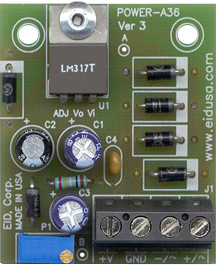
Adjustable Output Positive Voltage Power-Supply Kit (Adj. output 1.25V to 24 VDC) is an electronics board (kit) that allows you to connect up to 30V AC or DC on one side of the board and get adjustable VDC regulated on the other side. Every lab should have a few of these boards handy. The boards will allow you to easily power all your analog components (i.e. op-amp). The Terminal Block TB connector is included and makes it easy to use.
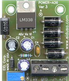
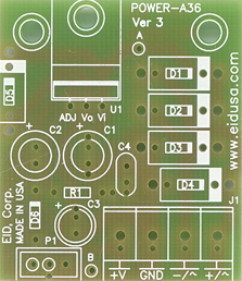
Standard Board With optional high-current configuration
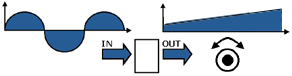
Basic operation of the adjusted voltage regulator board
The diodes bridge D1-D4, together with the capacitor C1, will convert input AC voltage to DC Voltage (See below kit drawing). Additionally, the diode bridge ensures that the polarity of the bridge output remains the same regardless of the input voltage polarity. It's what we call "dummy-proof." Let's say, for example, the board is powered by a 24V battery, the output polarity remains the same no matter how you connect the power to the board's diodes bridge.
The other side of the diodes bridge drives the voltage regulator U1. The adjustable voltage regulator is the main component of this kit (regulator). Usually having three legs, it converts varying input voltages of > 24 and up to about 30 VDC or VAC, and produces a constant regulated output voltage base on your settings (adjustment via P1).
The adjustable positive voltage regulator is available in a variety of packages for different outputs and max current driver. The most common part numbers of the adjustable voltage regulator is LM317 for an output of up to 1A with 1.25 to 24VDC output. This monolithic integrated circuit (IC), is an adjustable 3-terminal positive voltage regulator designed to supply more than 1A of load current with an output voltage adjustable over a 1.35 to 30V. The LM338 should be use with when circuit require output of up to 3A. and the the LM138 for up to 5A. See more info below. Heat sinking block is usually require when pulling current > 400mA (optional). Heat sink are manly manufacture from Aluminum material. One can use our die-cast aluminum enclosure, for both heat-sink device and enclosure to house its power supply and transformer.
The LM317, LM338 series of adjustable voltage regulators are designed for positive input. The adjustable regulator LM317 typically has the ability to drive currents up to 1A. Application requirements only up to 150mA, LM317 in a TO-92 packaging can be used. Ask our sales engineers for more details.
The LM317 series of adjustable 3-terminal positive voltage regulators is capable of supplying in excess of 1A over a 1.25V to 30V output range. They are exceptionally easy to use and require only two external resistors to set the output voltage. Further, both line and load regulations are better than standard fixed regulators. Also, the LM317 is packaged in standard transistor packages (TO-220 and T-92) that are easily mounted and handled.
In addition to higher performance than fixed regulators, the LM317 series offers full overload protection available only in IC's. Included on the chip are current limit, thermal overload protection and safe area protection. All overload protection circuitry remains fully functional even if the adjustment terminal is disconnected.
Normally, no capacitors are needed unless the device is situated more than 6 inches from the input filter capacitors in which case an input bypass is needed. We calculated a capacitor (C1) of 47uF for our input filter. It will be sufficient for both 50 and 60 HZ lines voltage. An optional output capacitor (C3) can be added to improve transient response and stabilization. In environment (industrial etc.) with high frequencies additional cap (C4) is require see text for more details. The adjustment terminal can be bypassed to achieve very high ripple rejection ratios, which are difficult to achieve with standard 3-terminal regulators. Adding 10uF across the ADJ pin (leg) will add stability when fast voltage swings is requires. Furthermore this cap (C2) is used as a low past filter (L.P.F. or LPF) and will alienate any frequency of above 6Hz at minimum output voltage, (F=1/2*PI*RC).
LM317 is useful in a wide variety of other applications. Since the regulator is "floating" and sees only the input-to-output differential voltage, supplies of several hundred volts can be regulated as long as the maximum input to output differential is not exceeded, i.e., avoid short-circuiting the output. Please be advised that our kit design for a maximum voltage of 30V. Also, it makes an especially simple adjustable switching regulator, a programmable output regulator, or by connecting a fixed resistor between the adjustment pin and output. For applications requiring greater output current, see LM338 series (rated up to about 3A) and LM138 series (rated up to about 5A) data sheets.
Some of the Features of the LM317 include: 1% output voltage tolerance, max. 0.01%/V line regulation, max 1A output current, adjustable output down to 1.25V, current limit constant with temperature, 80 dB ripple rejection, output is short-circuit protected.
As mentioned
above, the component has three legs: Input leg which can hold up to
36VDC (we recommend not to exceed 30V), Adjustable leg (ADJ) and an output leg with the regulator's
voltage. For maximum voltage regulation, adding capacitors C3
and C4 in parallel between the ground and the output is usually
recommended. C4 a 0.1MF capacitor is used. This eliminates any high frequency AC
voltage that could otherwise combine with the output voltage.
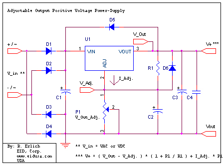
The protection diode D5 added to prevent C3, C4 combination from discharging thru the regulator during an input short circuit. The diode D6 protects against capacitor C2 discharging thru the regulator during an input short circuit. Therefore the combination diode D5, D6 prevents the C2 (adj. cap) from discharging thru the regulator during an input short circuit.
Final
Note:
As a general rule the input voltage should be limited to 2 to 3 volts
above the output maximum voltage. The LM317 series can handle up to 36
volts input, be advised that the power difference between the input
and output appears as heat. If the input voltage is
unnecessarily high, the regulator will overheat. Unless
sufficient heat dissipation is provided through heat sinking, the regulator will shut
down.
Kit Includes
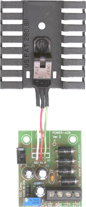
Note Replace the 1N40017 diode with 1N5006 and using LM338 (up to 3A) see above text for more details. The PCB is design to fit both diodes (extra holes locations and size to accommodated different diode sizes). For you convenient, we carry inventory of the 1N5006.
Schematic
Output voltage is set by two resistors ratio R1 and P1 connected as shown above. The voltage across R1 is a constant 1.25 volts and the adjustment terminal current is less than 100uA. The output voltage can be closely approximated from V+ = 1.25 * (1+(P1/R1)) which ignores the adjustment terminal current but will be close if the current through R1 and P1 is many times greater. A minimum load of about 10mA is required, so the value for R1 can be selected to drop 1.25 volts at 10mA or 120 ohms to be on the safe side, we recommend resistor of about 240 ohms. Something less than 120 ohms can be used to insure the minimum current is greater than 10mA.
When power is shut off to the regulator, the output voltage should fall faster than the input. In case it doesn't, a diode D5 connected across the IC input and the output terminals protect the regulator from possible reverse voltages. A 47uF electrolytic capacitor across the output improves transient response, and a small 0.1uF capacitor is recommended across the output (see above text). The power transformer should be large enough so that the regulator input voltage remains 2 to 3 volts above the output at full load.
For a particular output voltage (V+), you can replace resistor R1 and trimmer P1 combination with 1% resistors. For example use R1 = 340 ohms, and replace P1 with resistor value of 3.74K ohms, both in 1% tolerance. You will get very close to 15VDC output voltage. Ideally for single rail voltage require by many operational amplifiers (Op-AMP). Use R1 = 249 ohms and P1 = 750 ohms and get 5VDC output voltage, ideally for all your TTL and CMOS power needs.
Options
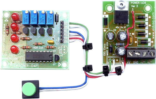
Switch 4 pre-set voltages simply by a pressing a push button (switch), see schematic below. Simply connect Ax and GND to point A and B on the main PCB respectively. The switching mechanism will replace P1 with 4 new predetermine voltages
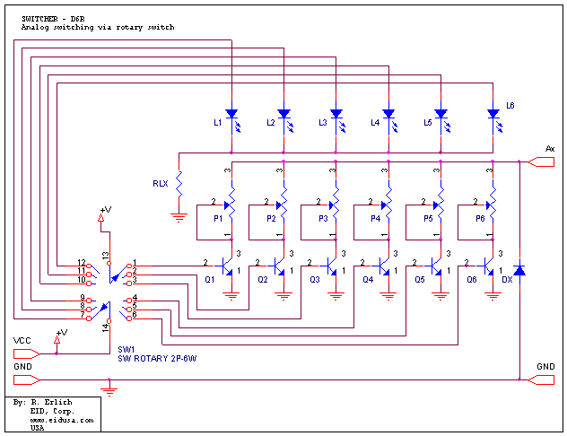
Finally for 6 predetermine voltages the see sch. below using 6 positions rotary switch.
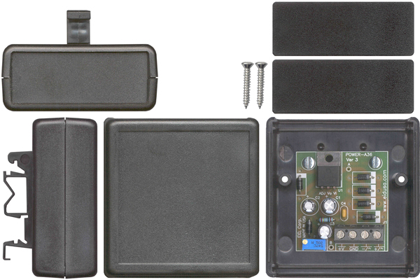
Mounting Option
Note: Use heat-sink (if needed). Additionally, Please be advised heat-sink, Din-Rail mounting clip, wires and transformer are sold as options.
Shown above high-current settings adj. power supply board with heat-sink and wires options.
For our line of transformers click Here
|
||
|
Description and SKU# |
Price |
Picture |
|
1.25-24VDC PS, Input up to 30VDC & adj. output 1.25V to +24V/1A, w/LM317 TO-220
EID-K-VRG-125X-24V-1A-ASM Fully assembled
EID-K-VRG-125X-24V-1A-KIT Kit |
48.99
37.99 |
|
|
1.25-24VDC PS, Input up to 30VDC & adj. output 1.25V to +24V/3A, w/LM338 TO-220
EID-K-VRG-125X-24V-2A-ASM Fully assembled with high current option
EID-K-VRG-125X-24V-2A-KIT Kit with high current option |
59.61
48.99 |
|
|
EID-K-VRG-125X-24V-XA-PCB PCB Only |
18.95 |
|
|
4 Voltages via one button kit
EID-K-VRG-SITCHER-D4P-ASM Fully assembled
EID-K-VRG-SITCHER-D4P-KIT Kit |
82.39
69.45 |
|
|
4 Voltages via one button kit
EID-K-VRG-SITCHER-D4P-PCB PCB only |
16.99 |
|
|
|
||