|
Industrial Wave generator Interface Board Module is an Original Manufacturing Engineering (OEM) industrial and commercial rated high performance, high efficiency board that utilizes Multi Turns Trimmer (potentiometer) to choose output wave at the following frequency of 50Hz, 60 Hz, 100Hz and 120Hz.
Low voltage waveform generator board the WAVER-5060100120A/B/C/D/X is an software driven integrated circuit capable of producing high accuracy sine, square, triangular and saw-tooth low voltage waveforms at predefined frequencies: 50Hz, 60Hz, 100Hz & 120Hz. Where, the output frequency can be selected via multi-turn-trimmer located on the board.
The wave output is stable over a wide range of temperature and supply variations.
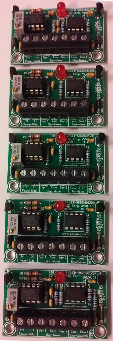
Model A Sine wave with LPF and amplitude of 5V
Model B 5V Sine wave and amplitude of 5V
Model C 5V Triangular wave and amplitude of 5V
Model D 5V Saw-tooth wave and amplitude of 5V
Model X Sine wave with output pre-set amplification (preset amplitude 0 to 10V)
Note: all above models have an additional two outputs with a 5V Rectangular wave. Where, each output is at the opposite phase to the other.
Let our OEM engineer’s custom “tailor” the frequency and the wave form to meet your application requirements and needs.
The board also contains indication LED for Power On (PWR ON) and Microcontroller Self Testing (MST). The LED will blink "like HEART BEAT" once every second, indicating all of the board functions are running and powered correctly.
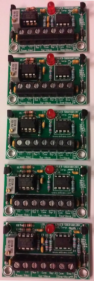
Shown above top to bottom Model A,B,C,D,X
The board offers the features needed for professional setting for industrial inverters.
Mounting is easy via two 0.156" mounting holes using 6-32 screws and wire (optional) via convenient conventional industrial standards locking connectors.
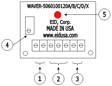
Shown above Wave generator @ 50/60/100/120Hz Interface Board Module basic connections illustration
1. External Power connections via terminal block type connector. Where; pins are marked (front left to right) Power (vdc) (+), Power (vdc) (-)
2. Square wave outputs connections via terminal block type connector. Where; pins are marked (front left to right) Sqr-wave Sqr1, Com, Sqr2
3. Sine, Sawtooth, Triangular wave (model depended) output connections via terminal block type connector. Where; pins are marked (front left to right) Sin/Saw/Tri-wave Com, Sin1/Saw1/Tri1
4. Main on board multi turn potentiometer output frequency select. Where; max-CCW to max CW output frequency change from 50Hz to 60 Hz to 100Hz to 120Hz.
5. Heart-Beat LED indication.
Model A:
Model B:
Model C:
Model D:
Model X:
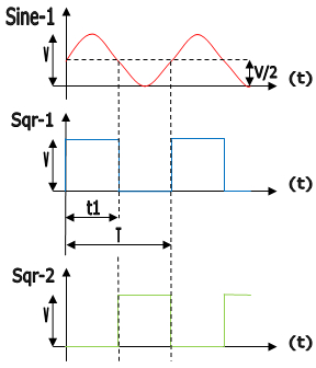
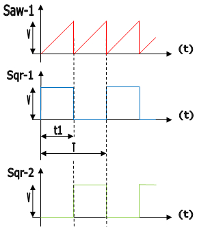
Model A, B & X Outputs:
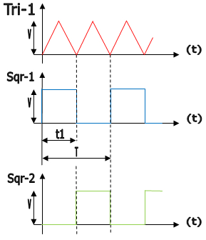
Model C (left) and Model D (right), B Outputs:
Where;
V=5V,
V/2=2.5V
T=20mSec or 16.666mSec or 10mSec or 8.333mSec
t1=T/2
Note: Model X the Sine output amplified so that V=10V and V/2=5V
Frequency = 1/T
==> Output frequency F=50Hz or 60 Hz or 100Hz or 120Hz
Standard Features:
● 4 Output frequency select via pot or external reference voltage (0-5VDC)
● High efficiency circuitry
● Conveniently front mounted terminal block connections
● Conveniently front mounted LED for both power on and Microcontroller Self Testing (MST) indicators.
Board Dimensions:
Board width, length, height: 2.00" * 1.3125" * 0.625"
Board Mouthing Dimensions:
Two (4) mounting holes (.156" Dia.) 1.70" on center.
Note: Use four (2) 6-32 screws and stand-offs to mount the board.
Caution: Do not mount the board where ambient temperature is outside the range of -10° C (15° F) to 45° (115° F). -20°C to +50°C (-4°F to 122°F).
Specifications:
|
||||||||||||||||||||||||||||||||||||||||||||||||||||||||||||||||||||||||||||||||||||||||||||||||||||||||||||||||||||||||||||||||||||
|
||||||||||||||||||||||||||||||||||||||||||||||||||||||||||||||||||||||||||||||||||||||||||||||||||||||||||||||||||||||||||||||||||||
