|


The
Pulse Type Transformers
600 to 602 series. P.C. Board Mount Encapsulated transformers
Key
Features (EID-600-EID-602 Series):
-
These
ferrite cored transformers are fully encapsulated in a high
grade black molded case with a UL94V-O rating.
-
Used
in digital and data processing, line coupling, matching,
isolation etc.
-
Working
voltage rating maximum of 500V D.C.
-
ET
values up to 50V uS.
|
P#
|
Turns
Ratio +/- 2%
|
Primary
Inductance uH (min)
|
Primary
ET Constant V uS
|
Inter
W Capacity p.f. Ref.
|
Leakage
Inductance uH max.
|
D.C.
Resistance Ohms max.
|
Cir.
Dia.
|
|
EID-600AA
|
|
|
|
|
|
|
|
|
EID-600BA
|
|
|
|
|
|
|
|
|
EID-600CA
|
|
|
|
|
|
|
|
|
EID-600PA
|
|
|
|
|
|
|
|
|
EID-602GA
|
|
|
|
|
|
|
|
|
601A
|
|
|
|
|
|
|
|
|
601B
|
|
|
|
|
|
|
|
|
601C
|
|
|
|
|
|
|
|
|
601D
|
|
|
|
|
|
|
|
|
601E
|
|
|
|
|
|
|
|
|
601F
|
|
|
|
|
|
|
|
|
EID-602A
|
|
|
|
|
|
|
|
|
EID-602B
|
|
|
|
|
|
|
|
|
EID-602C
|
|
|
|
|
|
|
|
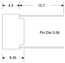
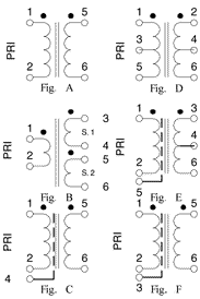
Mechanical & Schematic Data
(600 to 602 Series):
Note:
-
All dimensions in mm
- Pins 3 & 4 are omitted on circuit diagram A & B
units
|

|

|

Key
Features (610A & 610B):
-
These
ferrite cored transformers are fully encapsulated in a high
grade black molded case with a UL94V-O rating.
-
Units
are intended for wide band and pulse applications including
thyristor / triac firing circuits.
-
Peak
pulse voltage rating maximum of 250V.
-
Insulation
tested to 1,000V RMS.
|
P#
|
Ratio
|
Primary
|
Secondary
Resistance
|
Primary
ET Constant V (uS).
|
Leakage
Inductance uH (max.)
|
Max.
Primary or Secondary Current
|
|
Inductance
mH (min)
|
Resistance
Ohms
|
Sec.
1 (Ohms)
|
Sec.
2 (Ohms)
|
@
0.1% Duty
|
@
0.01% Duty
|
|
610A
|
|
|
|
|
-
|
|
|
|
|
|
610B
|
|
|
|
|
|
|
|
|
|
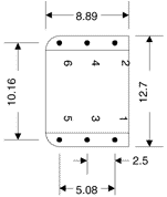
Mechanical & Schematic Data
(610A ):

Note:
All dimensions are in mm
Mechanical
& Schematic Data (610B):

Note:
All dimensions are in mm
Key
Features (610AA-610H):
-
These
ferrite cored transformers are fully encapsulated in a high
grade black molded case with a UL94V-O rating.
-
Units
are intended for wide band and pulse applications including
thyristor / triac firing circuits, signal isolation, line
matching, low power switch mode power supplies, etc.
-
Working
voltage rating maximum of 500V RMS
-
All
units are voltage proof tested to 2.0KV peak 50 Hz.
|
P# |
Ratio
|
Primary
|
Leakage
Inductance uH (max)
|
Capacity
pf. (Ref)
|
D.C.
Winding
Resistance (ohms)
|
Sch.
Fig. #
|
Remarks
|
|
Inductance
mH (min)
|
ET
Constant V (uS)
|
Pri.
|
Sec.
1
|
Sec.
2
|
|
610AA
|
|
|
|
|
|
|
|
-
|
|
-
|
|
610BB
|
|
|
|
|
|
|
|
|
|
-
|
|
610C
|
|
|
|
|
|
|
|
|
|
-
|
|
610D
|
|
|
|
|
|
|
|
-
|
|
610AA
plus electrostatic shield
|
|
610E
|
|
|
|
|
|
|
|
|
|
-
|
|
610F
|
|
|
|
|
|
|
|
-
|
|
|
|
610G
|
|
|
|
|
|
|
|
-
|
|
includes
electrostatic shield
|
|
610H
|
|
|
|
|
|
|
|
-
|
|
includes
electrostatic shield
|
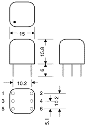
Mechanical & Schematic Data
(610AA-610H):
|

Notes:
- Pins 0.8 or .64 square
- Dot above pin 1
-All dimensions are in mm
-Pin 3 & 4 exist on 610BB, 610C & 610E |

|
|

