![]()
|
|
||
|
Every lab should have a few of these boards handy. The boards will allow you to easily rectify all your AC voltages. The Terminal Block TB connector is included and makes it easy to use.
Basic operation of the voltage regulator board
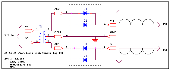
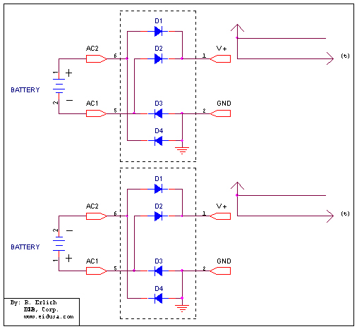
A full wave bridge rectifier (diode bridge) is an a circuit utilizing of four diodes in a bridge configuration to convert alternating current (AC) into direct current (DC), also known as full-wave rectification.
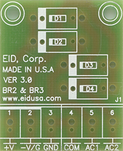
The diodes bridge D1-D4, will convert input AC voltage to DC voltages (See below kit drawing). Additionally, the diode bridge ensures that the polarity of the bridge output remains the same, regardless of the input voltage polarity.
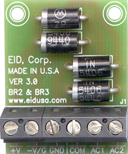
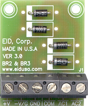
Model A Model B High current (up to 3A) Low current (up to 1A)
Schematic
Three main configurations can be achieve using the board:
Kit Includes
Option
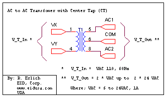
Transformer with central tap (CT) configuration, see schematic below.
|
||
|
Low current diode bridge kit (Model B), outputs up to 1A |
||
|
Description and SKU# |
Price |
Picture |
|
EID-K-BRIDG-ER-D1A-ASM Fully assembled |
18.00 |
|
|
EID-K-BRIDG-ER-D1A-KIT kit |
15.00 |
|
|
High current diode bridge kit (Model A), outputs up to 3A |
||
|
Description and SKU# |
Price |
Picture |
|
EID-K-BRIDG-ER-D3A-ASM Fully assembled |
24.00 |
|
|
High/Low current PCB |
||
|
EID-K-BRIDG-ER-D3A-KIT kit |
18.00 |
|
|
EID-K-BRIDG-ER-DXX-PCB PCB Only |
9.99 |
|
|
|
||