![]()
|
|
||
|
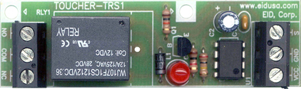
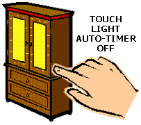
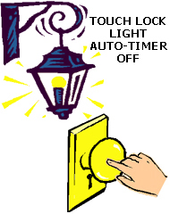
Tap on TOUCHER-TRS1. The easy single sensitive finger touch-pad relay switch kit. Our TOUCHER-TRS1 has many applications; Turn on for predetermine time light motor etc simply by touching sensitive metal pad. Use the kit anywhere you’d like to draw an audience and a smile show friend your magic-touch. The unique small design will allow you to mount kit almost anywhere. Operates from 9 to 12VDC (optional), or via one of our 9 or 12 battery simulator/regulator kits. The alternative uses are endless. It’s designed for the beginner as well as the expert. Please drop us a line at sales@eidusa.com and let us know the creative ways you and your friends use the TOUCHER!
Do It Yourself (DIY) and enjoy your kit!
Tap on TOUCHER
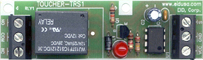
Touch-pad/wire sensitive relay switch with timer |
||
|
|
||
|
Schematic
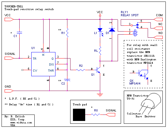
TOUCHER-TRS1 is our finger sensitive touch pad switch kit. It's based on the Integrated Circuit (IC) LM555 as a Mono-stable-timer. Trigger through Low Past Filter (L.P.F.) RX, C1 combinations, through pin 2 the Trigger pin (TR) of the timer.
F = L.P.F. @ -3dB = 1 / (2 * PI * R * C)
RL resistor determines the LEDs brightness and limits the current flow to about 10mA when running 12 VDC.
R2 resistor determines the minimum transistor forward base-current sufficient to turn the transistor on, therefore the LED and the Relay.
The
input trigger sets the LM555 internal flip-flop. The capacitor
C2 is begins to charge through resistor R1. As soon as the
charge equal 2/3 of the Rail-Voltage (+VCC, supply voltage), the
LM555 internal upper comparator triggers and resets its internal
control flip-flop. Pin 3 (output) switches back to zero.
C2 and R1 combination determines the time the transistor Q1 is "On", therefore the LED (L1) and the Relay (RLY1) "On" time.
Where;
T = Time period "On" = 1.1 * C2 * R1
For a particular needed relay and/or LED "On" time (T), you can replace resistor R1 and capacitor C2 as needed. For example use R1 = 10K Ohms, and C2=100uF. You will get about 1.1 second relay time on. Increase R1 to 100K and get 11 second etc.
When long "On" time (delay) required--you can increase either the electrolytic capacitors C2 and/or the value of the resistor R1. R1 may be as high as 1 Meg. However with high resistance values for R1 the leakage current of the timing capacitor C2 becomes a significant factor in the operation of the timer. The circuit can run for a long time, and never time-out if the leakage current is equal to the current through the resistor at some voltage. Therefore, when long delay is require, we recommend Tantalum-capacitor to be used. They have very low leakage current. The only problem with Tantalum capacitors that they are expensive and not available in large capacitance values. |
||
|
|
||
|
Description and SKU# |
Price |
Picture |
|
TOUCER-TRS1 Fully assembled
EID-K-TOUCHER-TRS1-ASM |
27.00 |
|
|
TOUCER-TRS1 kit
EID-K-TOUCHER-TRS1-KIT |
23.97 |
|
|
TOUCER-TRS1 kit PCB Only
EID-K-TOUCHER-TRS1-PCB |
12.99 |
|
|
|
||