![]()
|
|
||
|
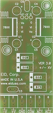
Dual Output 5 & -5 Voltage DC Regulator Kit is an Electronics board that allows you to connect 7 to 24V AC Center Trace (TC) or +/-7 to 24VDC on one side of the board and get dual regulated voltages, 5VDC and -5VDC on the other side. Every lab should have a few of these boards handy. The boards will allow you to easily power all your CMOS, TTL or Op-Amp components. The Terminal Block TB connector is included and makes it easy to use.
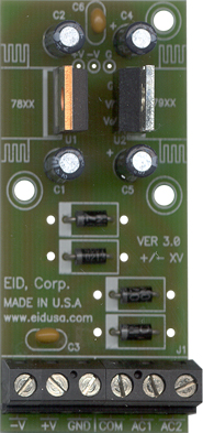
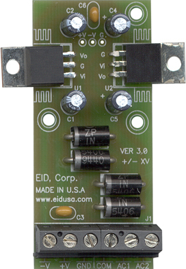
Standard Board With optional high-current configuration
Basic operation of the voltage regulator board
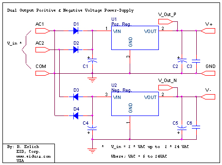
The diodes bridge D1-D4, together with the capacitor C1-C4, will convert input dual AC voltages to dual DC voltages (See below kit drawing). Additionally, the diode bridge ensures that the polarity of the bridge output remains the same, regardless of the input voltage polarity.
The
other side of the diodes bridge drives the voltage regulators U1
and U2.
The voltage regulators are the main component of this kit (regulators). Usually
having three legs, it converts
varying input voltages and produces a constant regulated output
voltage. They are available in a variety of outputs. The most common part numbers
of the regulator starts with the numbers 78 or 79, and finish
with two digits, indicating the output voltage. The number 78
represents positive voltage, and 79 a negative one. The 78XX series
of voltage regulators are designed for positive input. And the
79XX series is designed for negative input. The LM78XX and the LM79XX series typically has the ability to drive currents up to 1A.
Application requirements up to 150mA, 78LXX and 79LXX can be used. As mentioned
above, the component has three legs: Input leg which can hold up to
36VDC (we recommend not to exceed 24V), Common leg (GND) and an output leg with the regulator's
voltage (positive voltage for the LM78XX and negative for the
LM79XX). For maximum voltage regulation, adding capacitors C2,C5
and C3,C6 correspondingly in parallel between the common leg and the output is usually
recommended. C3,C6 a 0.1MF capacitor is used. This eliminates any high frequency AC
voltage that could otherwise combine with the output voltage.
Final
Note: As a general rule the input voltage should be limited to 2 to 3 volts
above the output voltage (LM78XX series) and 2 to 3 volts below the output
voltage (LM78XX series). The LM78XX series can handle up to 36
volts input and the LM79XX -36 volts, be advised that the power difference between the input
and output appears as heat. If the input voltage is
unnecessarily high, the regulator will overheat. Unless
sufficient heat dissipation is provided, through heat slinking, the regulator will shut
down.
Due to the regulator construction difference, use dual heat-sink (if needed), one for the LM78XX, and one to the LM79XX.
Kit Includes
Schematic
Option
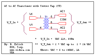
Transformer with central tap (CT) configuration, see schematic below.
|
||
|
5VDC and -5VDC PS, high current. Input up to +/-24V AC/DC, outputs +5V /800mA & -5V /800mA |
||
|
Description and SKU# |
Price |
Picture |
|
EID-K-VRG-P05V-N05V-01A-ASM Fully assembled |
46.00 |
|
|
EID-K-VRG-P05V-N05V-01A-KIT Kit |
34.00 |
|
|
5VDC and -5VDC PS, low current. Input up to +/-24V AC/DC, outputs +5V /90mA & -5V /90mA |
||
|
Description and SKU# |
Price |
Picture |
|
EID-K-VRG-P05V-N05V-XLA-ASM Fully assembled |
40.00 |
|
|
EID-K-VRG-P05V-N05V-XLA-KIT kit |
32.00 |
|
|
EID-K-VRG-PXXV-NXXV-XXA-PCB PCB Only |
18.00 |
|
|
|
||